Data center cabling installation

Data center cabling — fiber backbone, Cat6A copper & high-density rack infrastructure.

Enterprise data center cabling requires a different discipline from standard office networks — high connection density, strict airflow requirements, three-tier network architecture and infrastructure that must stay organized through constant equipment changes. Installed, OTDR-tested and fully documented.

  • OM4 multimode fiber backbone — 40G to 150m, 100G to 100m
  • Cat6A copper for server-to-top-of-rack switch connections
  • Structured rack organization — airflow-aware, color-coded, labeled
  • 100% OTDR testing with insertion loss documentation on all fiber
Data center cabling OM4 fiber backbone Cat6A copper OTDR tested Rack organization
OM4 & OS2 fiber
OTDR-tested all fiber
Full as-built docs
Live-environment capable
50+ U.S. markets
What data center cabling covers

Data centers demand a fundamentally different cabling discipline from standard commercial environments

Data centers connect thousands of network interfaces in a relatively small space — servers, switches, storage systems and management infrastructure all cabled together in high-density rack rows that must remain organized, serviceable and expandable for years without major disruption. Unlike an office environment where a single floor might have 200 cable runs, a medium-density data center room can have ten times that density in a fraction of the footprint.

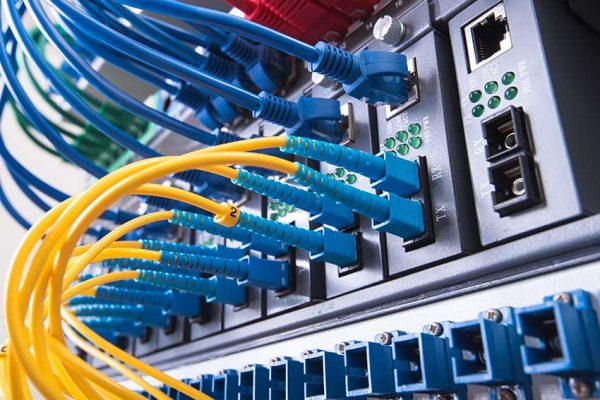
The two core cable systems in a commercial data center are fiber optic cabling and Cat6A copper. Fiber (typically OM4 multimode for intra-facility backbone, OS2 single-mode for longer distances) carries the high-capacity backbone traffic between core, aggregation and access layer switches. Cat6A copper connects individual servers to the top-of-rack switches within each cabinet row — handling the 10GBase-T server connections that form the majority of physical port count in most deployments.

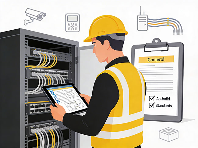
Every cabling decision in a data center — fiber type, run routing, cable length, management hardware, labeling convention — has downstream consequences for airflow, cooling efficiency, troubleshooting time, and the ability to add capacity without disrupting active infrastructure. Planning these decisions before pulling a single cable is what separates organized data center infrastructure from the tangled messes that create operational risk.

Why data center cabling is different
📐
Density changes everything

Hundreds of connections per rack row. Cable routing that blocks airflow causes cooling failures. Organization isn't aesthetic — it's operational.

🔄
Change is constant

Servers are added, replaced, decommissioned. The cabling must support these changes without requiring wholesale rework of existing infrastructure.

Uptime cannot be compromised

New cable runs added in live environments without disturbing active connections. Change management documentation maintained throughout.

🔍
Documentation enables speed

When an issue occurs at 3am, the team needs to find the right cable in seconds. Labeling, port schedules and as-built records make that possible.

Full scope of service

Every component of a commercial data center cabling installation

Data center cabling infrastructure has six distinct components — each requiring specific cable standards, routing discipline and documentation to produce an environment that stays organized and supportable under constant operational pressure.

01

Fiber Backbone — Switch Interconnects

OM4 multimode fiber links connecting core, aggregation and access layer switches — the high-capacity backbone that carries the bulk of traffic between network tiers and supports 40G and 100G uplinks.

  • OM4 multimode for intra-facility 40G/100G backbone
  • OS2 single-mode for inter-building or longer-distance runs
  • MPO/MTP trunk cables for high-density structured fiber systems
  • LC duplex patch cabling at equipment termination points
  • OTDR insertion loss testing on all installed fiber runs
02

Cat6A Copper — Server Connections

Cat6A horizontal cabling from servers and devices to top-of-rack (ToR) switches — the physical layer for 10GBase-T server connectivity inside each cabinet row.

  • Cat6A from servers to top-of-rack PoE-capable switches
  • Pre-terminated or field-terminated — planned before installation
  • Cable lengths cut to eliminate excess slack in rack environments
  • Color-coded by connection type or VLAN where specified
  • Fluke channel testing — every copper run documented
03

Fiber Distribution Frames (FDF)

Structured fiber termination panels organizing all backbone fiber connections at each layer of the network — providing clean patching points, clear labeling and organized cross-connect infrastructure.

  • FDF rack unit planning based on backbone port count
  • LC/APC or LC/UPC termination based on fiber standard
  • Port-to-switch schedule documentation
  • Color-coded fiber management per TIA-942 recommendations
  • Slack management and bend radius compliance throughout
04

Patch Panels & Copper Infrastructure

Organized Cat6A patch panels in each rack providing structured copper termination, cable management and the patching flexibility to support server moves, adds and changes without disrupting surrounding infrastructure.

  • Cat6A patch panels with 1U per 24 ports, planned by rack
  • Horizontal cable managers between every patch panel and switch
  • Consistent port numbering and labeling conventions
  • Patch cord color-coding by connection type
  • Port-to-server schedule documentation per rack
05

High-Density Cable Management

Overhead cable trays, vertical cable managers, J-hooks, fiber raceways and distribution frames — the cable management infrastructure that keeps organized environments organized under continuous operational pressure.

  • Overhead cable tray for inter-rack routing and fiber highways
  • Vertical cable managers in every rack — both fiber and copper
  • Hot aisle/cold aisle routing compliance for airflow preservation
  • Cable bundle sizing that supports PoE thermal performance
  • Expansion capacity built into pathway design from day one
06

Testing, Labeling & As-Built Documentation

100% OTDR testing on all fiber, Fluke channel testing on all copper, consistent port and cable labeling, and a complete as-built documentation package delivered at project close.

  • OTDR testing on all fiber — insertion loss results documented
  • Fluke channel testing on all Cat6A copper runs
  • Cable and port labeling at every termination point
  • Rack elevation drawings showing equipment and cabling layout
  • Full as-built package — fiber schedules, copper schedules, rack drawings
Cable types in data centers

Fiber vs copper — what each handles and when

Data centers use both fiber and copper, selected by connection type, bandwidth requirement and link distance. Getting this right before the design is finalized prevents expensive retrofits.

Primary backbone standard

Fiber Optic — OM4 & OS2

The backbone of every enterprise data center. Fiber carries switch-to-switch, switch-to-storage and inter-room traffic at speeds and distances that copper cannot match. OM4 multimode is standard for intra-facility runs; OS2 single-mode for inter-building connections or 400G+ requirements.

OM4 (multimode)40G to 150m · 100G to 100m · 400G to 50m
OS2 (single-mode)10G to 10km+ · 100G to 2km+ · unlimited reach
Connector typesLC duplex · MPO-12 · MPO-24
Testing standardOTDR — insertion loss & reflectance
Color (OM4)Erika violet jacket
Color (OS2)Yellow jacket
✓ Primary backbone choice
  • Core-to-aggregation switch interconnects
  • Aggregation-to-access layer backbone links
  • Inter-row and inter-room fiber highways
  • Storage area network (SAN) fabric connections
  • Inter-building campus fiber links
Server & device connections

Cat6A Copper — 10GBase-T

Cat6A is the standard copper choice for server-to-switch connections inside rack rows. It supports 10-Gigabit Ethernet to the full 100-meter channel distance, PoE++ at 90W for powered devices, and better thermal performance than Cat6 in the dense cable bundles typical of data center environments.

Speed10GBase-T — full 100m channel
Frequency500 MHz
PoE standardPoE++ (802.3bt) — 90W max
ThermalBetter than Cat6 in dense bundles
Testing standardFluke — TIA-568-C.2 channel
vs Cat6Cat6A required for 10G at full distance
✓ Server connection standard
  • Server NIC to top-of-rack switch ports
  • Out-of-band management (IPMI/iDRAC) connections
  • KVM and console switch connections
  • PDU and environmental monitoring device connectivity
  • Short rack-to-rack copper links under 100m
Network architecture

The three-tier data center network architecture

Most enterprise data centers use a three-tier network architecture — core, aggregation and access layers — with fiber backbone connecting the upper tiers and copper connecting servers at the access layer. Understanding this architecture before cabling begins determines the fiber port counts, patch panel placement, rack layout and cable routing for the entire project.

The fiber backbone connects core to aggregation and aggregation to access switches. Cat6A copper connects servers and devices to access layer (top-of-rack) switches within each cabinet row. Both layers must be planned together to produce a cabling infrastructure that supports the network topology.

Tier 1 — Core layer

Core Switches

The highest-capacity switching layer — high-port-density fiber switches connecting to aggregation switches across the facility. Core switches are typically located in a central MDF room or dedicated network room within the data center.

  • 100G / 400G uplinks to aggregation layer
  • OS2 or OM4 fiber depending on distance
  • Fiber distribution frame at each core switch location
  • Redundant switch pairs for uptime
Tier 2 — Aggregation layer

Aggregation Switches

Aggregation switches connect the core layer to the access switches in each pod or row — distributing traffic and providing the inter-row backbone. Typically located in end-of-row (EoR) cabinets or dedicated aggregation racks.

  • 40G / 100G uplinks to core, 10G downlinks to access
  • OM4 fiber between aggregation and access switches
  • EoR or dedicated aggregation rack placement
  • Fiber patch panels for structured cross-connect
Tier 3 — Access layer

Top-of-Rack Switches

Access layer switches sit at the top of each server rack — connecting individual servers via Cat6A copper and uplink to aggregation via fiber. Top-of-rack (ToR) placement minimizes copper run lengths within each cabinet.

  • 10G copper to servers via Cat6A within each rack
  • 10G / 25G fiber uplinks to aggregation switches
  • Cat6A patch panels below each ToR switch
  • 1U horizontal managers for copper patch organization
High-density environments

High-density data center cabling requires stricter organization standards

High-density rack environments — 40+ servers per rack, blade chassis, hyper-converged infrastructure — create cable management challenges that cannot be solved with standard practices. Airflow obstruction from unmanaged cables directly impacts cooling efficiency and failure rates. Untraced cables create maintenance risk when a change is needed under pressure.

HD
Structured overhead cable pathways

Dedicated overhead cable tray routing copper and fiber in separate defined paths — preventing congestion as rack density increases and preserving access to active connections below.

CL
Color-coded fiber and copper systems

Consistent color conventions per TIA-942 recommendations — making fiber tracing and port identification possible without documentation at hand, even in maximum-density environments.

LB
Consistent machine-readable labeling

Every cable labeled at both ends with a consistent identifier that maps to the port schedule — reducing mean-time-to-identification for any connection in the room to seconds, not minutes.

AF
Airflow-aware bundle sizing

Cable bundle diameters planned against airflow paths in hot-aisle/cold-aisle arrangements — preventing the cabling from becoming a thermal resistance that negates cooling infrastructure investment.

High-density data center cabling with organized rack rows and overhead cable management
Pre-installation planning

What must be confirmed before data center cabling begins

Data center cabling decisions made during installation — rather than in planning — create problems that persist for the life of the infrastructure. Fiber routes that were improvised create airflow issues. Copper lengths cut too long create cable management nightmares. Port schedules that don't exist create troubleshooting delays measured in hours. Confirming these items before mobilization eliminates the most common sources of long-term operational friction.

01
Rack layout and cabinet count

Floor plan showing rack positions, row arrangement, end-of-row vs top-of-rack switch placement, and hot-aisle/cold-aisle configuration — determines all cable routing paths.

02
Network tier architecture

Core/aggregation/access topology confirmed — including switch model, port density and uplink specifications — before fiber port counts and patch panel quantities are ordered.

03
Fiber type and connector selection

OM4 vs OS2, LC duplex vs MPO, pre-terminated trunk cables vs field-terminated — decided based on port density, link distance and speed requirements before any fiber is ordered.

04
Cable management hardware layout

Overhead tray sizing and routing, vertical manager specifications per rack, fiber raceway placement — all confirmed in the design stage to prevent airflow compromises during installation.

05
Labeling convention and port schedule format

Consistent naming scheme confirmed before installation begins — rack ID, position, port number — so every cable and port is labeled identically and the documentation is useful from day one.

Data center cabling planning and rack organization
Frequently asked questions

Questions about data center cabling

Technical answers for IT directors, data center managers and network engineers planning cabling infrastructure for enterprise and commercial data center environments.

What types of cables are used in data centers?

Data centers use OM4 multimode fiber for intra-facility backbone connections (40G to 150m, 100G to 100m), OS2 single-mode for longer distances and inter-building links, and Cat6A copper for server-to-top-of-rack switch connections supporting 10GBase-T. High-density environments may also use MPO/MTP pre-terminated trunk assemblies for structured fiber distribution frames.

What is OM4 fiber and when is it used?

OM4 is the standard multimode fiber for intra-data-center backbone links — supporting 40G Ethernet to 150 meters and 100G to 100 meters. It uses the erika violet jacket for easy identification. OM4 is appropriate for most commercial data center backbone applications. OS2 single-mode is used where link distances exceed OM4 limits or where 400G+ bandwidth is required.

Why is cable organization critical in data centers?

Data centers contain thousands of connections in a small space. Unmanaged cabling obstructs airflow — directly increasing cooling costs and failure risk. It makes troubleshooting exponentially harder, increases accidental disconnection risk during maintenance, and makes future expansion nearly impossible without rework. Organization with consistent routing, labeling and color-coding is a fundamental operational requirement.

What is OTDR testing and why does it matter?

OTDR (Optical Time Domain Reflectometer) testing measures insertion loss, reflectance and any faults along installed fiber runs. Every Cablify fiber installation includes OTDR testing on 100% of runs, verifying each link meets its insertion loss budget for 10G, 40G or 100G applications before the project closes. Results are documented and delivered with the as-built package.

Can Cablify work in a live data center without causing downtime?

Yes. Most data center cabling projects take place in live environments where active servers and network equipment cannot be interrupted. New cable runs are added alongside existing infrastructure without disturbing active connections. Maintenance windows are used only where absolutely required, and detailed change management documentation is maintained throughout to protect the operating environment.

What documentation is delivered at project close?

The as-built package for a data center project includes: OTDR test results for all fiber runs (insertion loss per run), Fluke test results for all Cat6A copper, rack elevation drawings showing equipment and cabling layout, fiber and copper port schedules mapping every cable to its source and destination, and the labeling legend covering all naming conventions used throughout the installation.

Start a data center project

Need data center cabling scoped for an enterprise environment?

Share the rack count, room layout, network architecture (fiber types, switch tiers), copper scope, timeline and whether the environment is live during installation — and the team will follow up within one business day.

Request a Data Center Cabling Quote

Tell us about your environment and infrastructure scope — the team will review and follow up within one business day.

Helpful details to include

Rack count and floor plan, network architecture (core/agg/access switch models), fiber type requirement (OM4 vs OS2), copper scope (server count per rack), cable management hardware preferences, whether the environment is live, and project timeline.

SCOPE: OM4/OS2 fiber · Cat6A copper · FDF & patch panels · Cable mgmt · OTDR + Fluke testing · As-built docs